Name: Mamute
Year: 2012
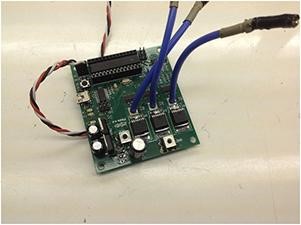
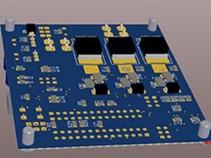
Project: In order to follow the evolution of the team and replace the middle project, the Mamute 1.1 plate was designed for robots in the middleweight (120lb) and lightweight (60lb) categories, in order to make them more reliable, with less need for maintenance.
Because of the high current peaks that can exceed 200A, this is the only one, of the new electronics, that controls only one motor and uses MOSFETs in the power part. The MOSFETs used support up to 240A, being the most powerful among their peers. Also on this project was added on-board programming of the microcontroller, 20MHZ crystal, use of cooler, screws for ring connector, PI filter and SNUBBER circuit.
The project was launched at Robogames 2012, where it proved to be efficient and at the same time very reliable. Seeking the evolution of the project, the team has already started to think about its optimization to solve small problems presented during the competition.

Name: Grifo
Year: –
Project:
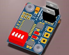
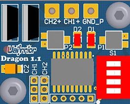
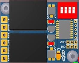
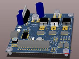
With the evolution of the beetleweight category, Vespa electronics no longer supplied the current required for the robots’ locomotion engines. Soon it was necessary to develop a new electronics, called Grifo 1.0.
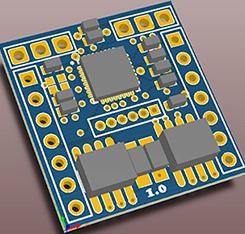
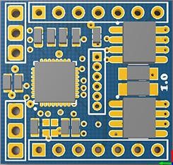
For Grifo’s switching, MOSFET’s were used that support up to 15A continuous and with small encapsulation. A novelty for the team was that this component uses BGA solder.
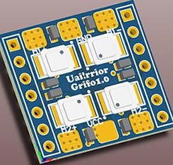
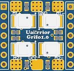
Due to the very limited space of the robots in the beetleweight category, the solution was to return to the electronic sandwiches, thus, two plates were designed, one for the power part and another for the control, both connected by a pin bar. In this way it was possible to design an electronics 21 × 22 [mm] in length.
Name: Rino
Year: 2013
Project: The Rino electronics was developed with the aim of replacing the Gorila and Javali electronics. These presented problems with the H bridge drivers, which suffered stresses due to recurrent current peaks from use during combat, causing the burning of the components.
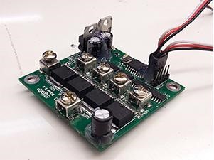
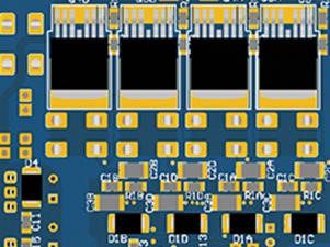
Rino electronics are used in robots in the hobbyweight categories, where robots weighing up to 12lb, Featherweight weighing up to 30lb, and Hockey-Pro, weighing 15lb, compete. This electronics controls two DC motors and has a circuit similar to the Mamute electronics. It is formed by a microcontroller that receives the signal from the receiver according to the control instructions made by the pilot and, through drivers capable of switching two complete H bridges, feed the locomotion motors through MOSFET’s.
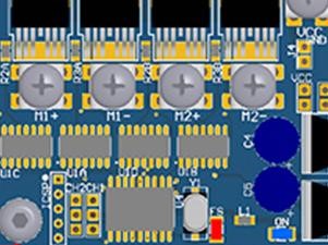
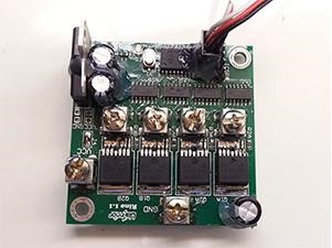
It made its debut at Winter Challenge 2013 and since then it has been shown to be efficient and reliable, as it supports current levels of up to 240A, light and compact, with dimensions of 59 × 60 [mm], it fits very well to the needs of the categories that are used.
Name: T-REX
Year: 2013
Project: The T-REX is an electronics that was used in the weapons of the robots of the lightweight and middleweight categories, the Federal M.T. and General respectively. T-REX came to replace the Arma 2.1 electronics, an electronics that was unreliable, because in some rounds the MOSFET’s would burn in “open”, firing the weapon, so it was necessary a new project that would solve the problems of the old electronics.
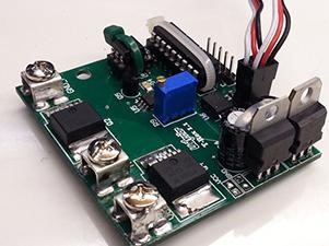
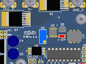
In the new project, the discrete MOSFET’s were replaced by SMD’s. Two MOSFETs were also added, with this change, their internal diodes, also called Freewheeling diodes, were used to protect the electronics against motor voltage spikes caused by the electromotive force.
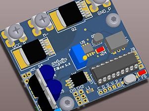
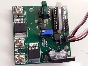
When the weapon mechanism suffers some damage, a current spike occurs, which applied over a long period can burn the engine. In order to prevent this from occurring, sensing is performed, which cuts off the weapon’s power supply, thus preventing further damage.
Name: Telemetria
Year: –
Project: Telemetry is a technology responsible for the remote control of events that occur on a machine during its operation. It is basically a technique of obtaining, processing and transmitting data. Through telemetry you can monitor everything that is happening internally on your machine, such as the current being sent to the motors, the battery voltage, etc. It is a technology widely used in motor sports and, more over, it is being widely used in the transport industries.
For the Uairrior team, Telemetry is an efficient way to have more precise information control than what happens internally with the robots during the combat, thus bringing greater security and confidence to the team, who will be able to check in real time its operation. This, with the use of this information we will be able to check which problems, or possible problems that may occur and avoid or solve them in the best possible way.
Logically, the pilot will have access to this information and it dictates what actions he should take during the combat.
Basically Uairrior Telemetry aims to monitor locomotion and weapon currents and also inform battery voltage. This communication is made in the following way: there is an electronics designed by the Team itself that is connected to hall window sensors, in this way, the power cables that go to the motor pass through this sensor and it identifies the current that is passing to that he can send the information to the electronics.
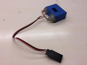
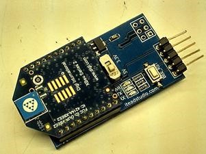
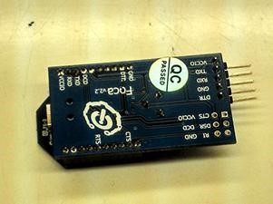
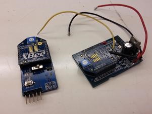
Therefore, the designed electronics are responsible for reading this signal and amplifying it. Once this is done, the amplified signal is sent to the XBee shield and it will be responsible for making wireless communication with the monitoring software. This communication is relatively simple. The shield connected to the Telemetry electronics sends the signal (wirelessly) to another XBee shield, this second is connected to a third electronics that converts the signal from serial format to be read in a USB port.
It is through this USB port that the computer will receive the final information about the current. This information is sent to a software (also developed by the Team) that in addition to presenting the graphics referring to the currents and battery voltage, it also receives images from a video camera that records the fight in real time, this is important for the responsible for monitoring can know what is causing the variations in the current.
Anyway, it is easy to see how advantageous this information is, especially for the pilot, who will have much more security during combat and will take the right actions at the right time.
We can conclude that telemetry is a technology that brings much more confidence and security, in addition to providing a broad knowledge about the machine with which it is working, which is extremely important and effective, especially when it comes to the Robot War, since during a fight several things can happen with the robot and it is necessary to be prepared for any possible problem. After all, as they say: “you never know what can happen inside the arena”.
Name: Vespa
Year: 2012
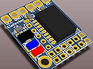
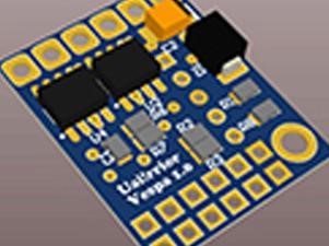
Project: The Team, aiming to expand its area of operation, decided to participate in the combat categories antweight (1lb) and beetleweight (3lb), and as the main obstacle found in these modalities is the small space and the weight limit, it was The Vespa project was created, which is only 20 × 25 mm long and has the capacity to control 2 DC motors.
Seeking to minimize and optimize the project, after a series of research done by the team, a SOIC encapsulation of the PIC16F628A microcontroller was used, contributing to the reduction of the size of this electronics. As they use small motors with low current consumption, it is possible to use full bridge integrated circuits to make the power part of the board, for Vespa the team opted for an SMD CI that controls an engine and has a maximum current of 3.5A , enough for these small fighters.
In order to compete also in the autonomous categories, pins were placed for the connection of external sensors in the electronics, thus being the first capable of being used, both in the radio controlled and in the autonomous categories.
His debut was at RoboGames 2012, reaching all expectations of the Team and bringing a world title with the robot Carrapato in the autonomous category, thus showing the great potential of the Team’s electronics.
Name: Javali
Year: 2012
Project: Some aspects of the plaque were mentioned in the Gorilla’s description, so the information here is specific to Boar electronics.
Intended for robots in the hobbyweight category (12lb), it has a reduced size (60 x 51 mm), power plans with less thickness and connections in the power area for welding the connection wires, battery and motors used, which consume less than 25A in this category.
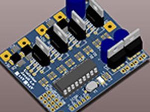
Being the most evolved electronics for the hobbyweight category, the Javali 1.0 project debuted at RoboGames 2012, where it presented an excellent performance, reaching all expectations of the Team.
Name: 3X4
Year: –
Project: With the reduction of the robot’s internal space, the need arose to adapt electronics that were smaller and controlled the motors efficiently and reliably. Therefore, several ways to reduce the circuit were evaluated and, among all, the one that best fit was to find a CI that would replace the H bridge. It and all its components are responsible for about 60% of the total size of the electronic board.
The H bridge is the electronic structure capable of reversing the motor’s direction of rotation, without having to reverse the polarity of the voltage source, in this case, the battery. Roughly speaking, this structure is composed of 4 keys operated in pairs, arranged similarly to the letter “H”, hence the name bridge H.
Upon research, an IC that was suitable for the current and operating voltage of the circuit, the MC33887, was found. In addition to having an H bridge internally, it has protection against current, voltage and temperature above nominal conditions. It is small and its encapsulation is 20-pin HSOP SMD, which makes the layout even smaller.
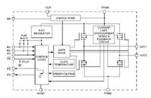
Following the specifications of the MC33887 datasheet and adapting it to the Uairrior control circuit, the circuit was designed and then the board layout. As the final size of the electronics was (35 × 46) mm, it was nicknamed “3 × 4 Electronics”.
In practice, this card worked as designed; driving two motors with a maximum output current of 5A. As an improvement for the next board, we are looking for a CI with greater current capacity, since this H Bridge technology has been tested and approved.
Name: Modular
Year: 2010
Project: Uairrior electronics, over the years of research and design, have evolved significantly. Made with components with great capacity to dissipate power and sensor and protection circuits that acted to minimize the effect of overvoltages and overcurrents. However, due to the high current demand and the high possibility of short circuits caused by metal chips, the circuit needed maintenance. Thus, the idea arose to make a plate that is easy to maintain and replace, that was small and reliable.
In the project, for each H Bridge controlling an engine there is an aggregate control circuit. As each robot has at least two motors, if a bridge does not work, the other module would not need to be replaced, hence the name Modular Electronics.
The circuit itself has not been changed, only a few protections have been added, for example, the TVS (transient voltage suppressor), a component responsible for absorbing voltage spikes. The size of the copper tracks was increased and, through calculations, it was found that a minimum of 2 oz of thickness would be required.

At (80 × 58) mm, its layout was entirely designed on the National Instruments Ultiboard. The topology of the components follows current levels, symmetry, visual character and ease of maintenance.
Initially made for 120lb robots, the Uairrior Modular Electronics has already been used in a 30lb featherweight robot, due to its small size and reliability. Used since the Winter Challenge 2010. The team has been working on more protection circuits and improving the control circuit used, bringing this circuit more and more to a professional level. It is certainly an electronics to take as a base for the current ones.
Name: Mini
Year: 2008
Project: The national robot war competition has grown over the years, mainly with the creation of new categories, such as hobbyweight (12lb), in 2007 and featherweight (30lb), in 2008. The Uairrior team could not stop growing together with the competition and overcome this challenge for electronics.
With the completion of the development of a complete electronics for the robots of the middleweight category (120lb), the team proposed to design a miniaturization of the plates, so that they could be used in the smaller robots, but maintaining the same reliability already achieved.
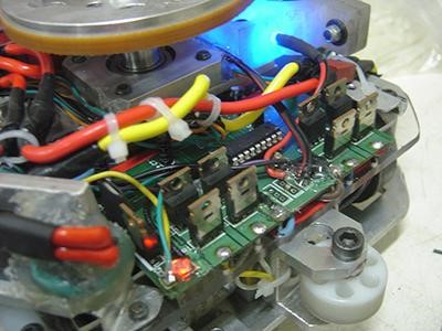
Some of the parameters to be considered were the size, which should be compatible with the category of the robot, the maximum power, since the engines would need less power, among others. To this end, the team decided to use SMD components (Surface Mounted Devices), change the logic part of the control and develop a layout that encompassed the three boards in one.
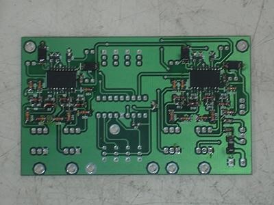
Then the research phase started, mainly about which components should be replaced, in which places it would be possible to obtain these components, the compatibility with the discrete components, among other things. With that, it was possible to assemble a prototype, test the circuit and discover possible failures.
Finally, the electronics project was adapted to the two robots of the Uairrior team that were under development at the time, the Butcher robot, in the hobbyweight category, and the UFO robot, in the featherweight category. Several tests were carried out in order to test the electronics limits and it was found that these circuits could be used with the reliability that the team needed in its projects.
Mini electronics were used to control UFO and Butcher robots in the 4th Winter Challenge, which took place in Amparo, in July 2008, obtaining 3rd place in the featherweight category, in addition to 3rd place in the middleweight category with the “sandwich electronics”.
Name: Sandwich
Year: 2007
Project: In 2007, after completing the work of the control board, the Uairrior team focused on making power electronics, which had a higher degree of complexity and involved a higher cost for its development.
At the time, the team used the OSMC (Open Source Motor Control) board and had thoroughly studied its operation. With that, it was decided to adapt the circuit of this board to the use of Uairrior, in order to optimize the project.
After an arduous research on which components to use, which modifications would be made, among other things, it was decided to use power Mosfet type transistors to drive the motors, protect the control circuit and a different logic to power driver.
A Protoboard was used to make several tests on the resulting circuit and to find possible defects. After some adjustments, it was successful and a new phase in electronics started: the making of a layout that would meet the needs of the projects developed by the team.
Some prototypes were developed for testing and correcting possible errors. The team used one of these prototypes during the 3rd Winter Challenge, which took place in 2006, in the city of Amparo, after all this is the best test to find possible defects that could not be simulated.
So, data were collected on the problems found in the electronics after the event, and the main problem was related to the communication between the control and power boards, due to the use of wires for this purpose.
Research was carried out in this area and, finally, the team found a solution: replace the use of cables with connectors, so that the power boards are directly connected to the control board. As a result, each of the power boards started to connect to one side of the control board, forming what was known as “sandwich electronics”.
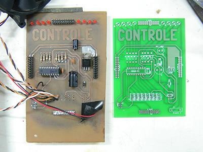
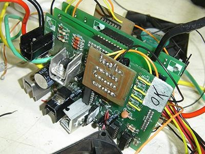
It was noticed, after tests, that communication was not impaired and there was still an improvement in the mechanical resistance of the plates. New simulations and tests were carried out to prove the efficiency of this project and thus, it was used during the 6th ENECA (National Meeting of Control and Automation Students), held in Curitiba – PR, in September 2006.
Still, the project was not finished. Improvements were developed to offer greater reliability to the project, which are related to both hardware and electronics software, in order to allow the maximum power estimated in the team’s initial proposal to be used.
In this way, the Uairrior team finalized its electronics project in 2007, which is known as “sandwich electronics”, thus being one of the first teams to develop a complete electronics for the middleweight (120lb) category, totally reliable and easily adapted to the team’s projects. This electronics provided us with a lot of knowledge to improve current projects.
Name: Control
Year: 2005
Project: Aiming to improve their projects, the Uairrior team started in 2005 its work for the construction of its own electronics, which provide greater freedom for the creation of robots, in addition to adding great knowledge to the Team members.
In order to facilitate the work, the electronics were divided into two parts: Power and Control, and the team opted to start the process by the latter, due to its less complexity and cost of components involved.
Studies and data were collected on the parameters of this project, such as the signal that would be sent to the engines, the reception of the control signal, among others. With that, it was decided to use a microcontroller, more precisely the PIC 16F628.
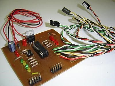
The team focused their efforts on programming the microcontroller and designing the layout of the control board. After this phase, tests were started on the robot that was under development by Uairrior at the time, o Vingador.
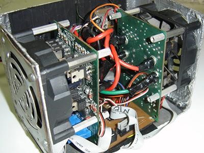
In this phase of testing and improving electronics, O Vingador presented major interference problems, caused mainly by the combustion engine used in the weapon. It was necessary to carry out several tests to identify the problem, the solution occurred after modifications in the board and, mainly, in the microcontroller software.
After some adjustments, the electronics were finally ready to be used in the 1st Winter Challenge, in 2005, held in Campos do Jordão. The team obtained 2nd place with the Vingador robot, transforming Uairrior into one of the pioneers in microcontroller electronic projects.